Custom Search

Free Blender tutorial : Blender User Interface

Introduction


Blender in Action

If you are reading this tutorial, you are probably feeling like I did exactly one year ago. I had found this extremely interesting looking 3D application (which other users were raving about), but the user interface completely baffled me. I couldn't find the quit function (I had to kill the application instead of exiting it), I saw buttons that seemed to react differently each time I clicked on them and every time something interesting happened, I could not reproduce it.

In the weeks after that, I slowly found out the basic principles behind the Blender user interface. And though it is non-standard, it became clear that it was a very consistent system - it would let me use the same functions in a number of completely different situations.

This tutorial will save you weeks of frustration by explaining the basics of Blender's user interface. It will not explain every button or even every window in detail (that is where the Blender manual comes in), but instead let you see the basic idea behind it.

After finishing this tutorial you are ready to work with the rest of the book. Like me, you will find out that Blender's user interface really grows on you; it is one of the most efficient and well-thought out interfaces I have worked with. MORE

free 3ds Max 2010: The Graphite Modeling Tools – Day 1

Jul 27th in 3D Art, Autodesk 3Ds Max by Kaleb Aylsworth
3ds Max 2010 introduces a vast array of new tools and features, not the least of which, are the new Graphite Modeling Tools. In this two part tutorial video tutorial series, professional game environment artist, Kaleb Aylsworth, will walk you through all of these new tools, and show you how to use them effectively in a practical, every day workflow.

In the first part of the series, Kaleb will spend over an hour demonstrating a majority of the tools and their various functions, and in the second part, he will spend two hours modeling a tropical jungle tree, using the graphite and freeform modeling tools in place of his traditional methods.
This is part 1 of the series: The Tools, and Their Functions.
Final Effect Preview READ MORE

free Maya modeling tutorial : Using Revolve

Revolve takes a nurbs curve, spins it kind of like pottery, and makes a complete 360 degree object.

Set-up
Set the menu set to surfaces.Make sure you're familiar with basic nurbs curves and basic polygons.
Creating The Profile Curve
This is the profile of whatever object you're making. In this tutorial we're making a glass.
Profile curves are made with nurb curves.
Step one - Go to create>CV curve tool.
Step two - Create the profile of the glass on one side.

Step three - By default the pivot point will be set to the center of the scene. Since the pivot point is the point at which the revolve function will revolve the surface around, it's important that it sits in the right place. In this case, it is in the center of the scene (origin). MORE

free Maya modeling tutorial : Creating End Tables

This tutorial covers basic polygonal primitives modeling with bevels.
set-up
Set the menu set to polygons.Make sure you're familiar with the move and scale tools.To create a polygonal object primitive go to create>polygon primitives>..
Modeling
Step one - Create a cube and scale it so it's the same size as the cube in the image below.
Step two - Right click on the model and go to edge component mode
Step three - Select the vertical edges on the corners.<
These will be the corners we bevel. MORE

free Maya tutorials: Chain gun in Maya tutorial

Written by Dzordz
Thursday, 21 December 2006
Page 1 of 3

In this tutorial I’ll show you how to model a chain gun and control rig for firing and aiming using basic MEL scripts.

First we will create base. Create Linear CV curve.


Then go to surfaces/revolve option box, set y for axis.


Revolved surface will look like this


Create upper parts, using same tool


Then from side view create one linear curve, that has same start and end point (use curve snapping or c key+mmb drag)


Then go to revolve option box, but set angle to 10.


This will create only 10 degrees out of circle.
MORE

free maya tutorials : Baking Ambient Occlusion Using Mental Ray

Written by Dzordz
Saturday, 10 February 2007
Page 1 of 2
Ambient occlusion can be very useful for adding details to shadows of your images.
But also it can be extremely expensive to calculate for every frame of your animation.


Ambient occlusion can be very useful for adding details to shadows of your images.
But also it can be extremely expensive to calculate for every frame of your animation.
If you have scene that is very static (camera flying trough environment), you can render ambient occlusion to texture and assign that texture to ambient attribute of your shaders. That way the scene will render very fast.
Before entering this tutorial I recommend you to read my tutorial for making lava shader, to get basic knowledge about hypershade and texturing in Maya.
In our example I modeled simple terrain using poly plane and one bridge going across. I also added one directional light (sunlight).
For texturing I used Photoshop. Here’s one very useful tip if you are going to use Photoshop for texturing. Assign lambert to plane (ground plane) and go to hypershade. Select plane and lambert you just assigned to it. Then in hypershade menu go to edit/convert to file texture (Maya software). Set bake shading group lighting. This will bake illumination to texture. Also surface shader is created and assigned to object. Delete that surface shader, and assign lambert to plane. Baked texture is located in sourceimages subfolder of your project. MORE

Free : How to Sketch a Line in Three Dimension or in Space?

In order to draw the axes for three dimension, we look at the Cardinal direction and we draw the vertical axis which is called the Z-axis in the North direction. Then we draw the X-axis in the South West direction, the Y-axis in the South East direction,the negative X-axis in the North East direction, and the negative Y-axis in the North West direction. Please click on the image for better understanding.

  • Step 2

    We would like to plot two points, the point P at coordinates (5,7,3) and the point Q at coordinates (-2,3,4). We are then going to draw a line through these two points.To do so, we go five units along the X-axis and then draw a line parallel to Y-axis that intersect the X-axis at x=5. Please click on the image for better understanding.

  • Step 3

    We would like to plot the point P at coordinates (5,7,3).We go seven units along the Y-axis and then draw a line parallel to X-axis that intersect the Y-axis at y=7. Please click on the image for better understanding.
  • Step 4

    We now draw a line from the origin of the axes O, that has coordinate (0,0,0) to the point where both the line X=5 and the line Y=7 intersect. That point R has the coordinate (5,7,0).
    We now draw a vertical line from the point (5,7,0) parallel to the Z-axis.
    We go to the Z-axis and at z=3, draw a line parallel to the line that connects the point (0,0,0) and (5,7,0). Wherever that line intersects, the vertical line from the point (5,7,0) that is parallel to the Z-axis, that intersection is our desired point, P. Please click on the image for a better understanding.
  • Step 5


    In order to have a better understanding, we can visualize a point in three dimension as the corner of a box. If we look at the image for this step #5 we see a corner of the box defined by the point P(5,7,3). Please click on the image for better understanding.

  • Step 6


    Similarly, To plot the point Q at coordinates (-2,3,4), We follow the instructions given in the previous Steps. That is we are going to draw a line at x= -2 parallel to the Y-axis, Then we draw a line at Y=3 parallel to the X-axis the point S where the line X=-2 and the line Y=3 intersect has coordinate (-2,3,0). Please click on the image for better understanding.

  • Step 7


  • Now, from the point S(-2,3,0) we draw a vertical line parallel to the Z-axis that is four units in length. The point Q is (-2,3,4). Please click on the image for better understanding.

    MORE

    free 3D design basics

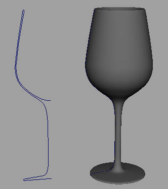
    Line Space and Form are the basic ingredients of 3D design.


    linecharacter.jpg


    Line has character. Line begins as the distant between two points. Like a path.


    richardlong02.jpg


    Richard Long 2003


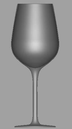
    Lines take shape to become 3-dimensional forms.


    deborah-butterfield.jpg


    …in wood..


    dbutterfieldgesture87.jpg


    in metal…..Deborah Butterfield, 1987.


    evahesse2.jpg


    Geometric and organic lines combine to interesting results. Eva Hesse, American Sculpture.


    sol-lewitt-thumb.jpg

    MORE

    free 3D Design Magazine Data Conversion Article

    3D Design Magazine's "In The Lab", features Okino's PolyTrans 3D data translation product. This is the second article written by Brendon Perkins on our PolyTrans software; the first review can be found here.


    [Page1][Page2][Page3]

    As an introduction to 3D data conversion, Mr. Perkins writes:

    "If you work in 3D, chances are you rely on multiple software applications to complete your work - modeling, animation, rendering, image processing, and video editing apps; perhaps more than one of each. So it's interesting to note that no file format standard is accepted throughout the industry for exchanging 3D data among applications. On the other hand, it's not likely that one will emerge. Tool developers strive to create marketable advantages for their tools, and these advantages are reflected in, or implemented as, mutually incompatible file formats.


    In lieu of a standard exchange format, most applications provide a limited set of import and export routines. But these routines usually don't provide a complete solution. In many cases, they don't account for intricate differences between formats that might help optimize models for the target application. Furthermore, they rarely deal with anything other than geometry. If you need a complete conversion that includes texture maps, animation paths, and the like, the usual import/export routines fall short.

    The single fact is that converting between 3D file formats isn't a straightforward task, and vendors have little incentive to develop top-notch conversion utilities. Consequently, there's room in the market for specialized file format conversion applications." More

    All free : What is virtual reality ?

    Applications

    Virtual Reality can be applied to all fields
    Mechanics, architecture, engineering, construction, automobile, electronics, geophysics, armed forces, aeronautics, highway construction and maintenance, transport, medicine, training, games, chemistry, museography, etc.

    Digital Scale Modelling and Virtual Prototypes

    Advantages :
    • Time and money savings
    • Internal and external real-time coordination aid – different teams can work together in real time on a modifiable prototype to facilitate comprehension and consensus
    • Pre-design testing
    • Simulation testing in realistic conditions
    • Unlimited scope for prototype alterations
    • Transportable prototypes
    • Variable-scale prototypes

    Read more

    All free : The Most Realistic Virtual Reality Room in the World and HSL's Thoughts on the Future of Combining Telepresence and Virtual Reality

    Owa State University has rolled out a six-sided Virtual Reality Room with 2Xs the number of pixels than any other virtual reality room in the world. The full press release can be found Here and my excerpts and thoughts on the future of combining telepresence and virtual reality are below.

    Iowa State Virtual Reality Room.jpg


    Newswise -- More than $4 million in equipment upgrades will shine 100 million pixels on Iowa State University's six-sided virtual reality room.

    That's twice the number of pixels lighting up any virtual reality room in the world and 16 times the pixels now projected on Iowa State's C6, a 10-foot by 10-foot virtual reality room that surrounds users with computer-generated 3-D images. That means the C6 will produce virtual reality at the world's highest resolution.

    Iowa State's C6 opened in June 2000 as the country's first six-sided virtual reality room designed to immerse users in images and sound. The graphics and projection technology that made such immersion possible hasn't been updated since the C6 opened. More

    button button

    Add to Google